Arm (Assembly Part 3)
Disclaimer: Shutter can be built using this bearing, which has 6 holes on each ring, or this one, which has 4. The images in this guide are using bearing with 6 holes, while the videos use the one with 4. The only differences between the two are the amount of hardware required, and which holes are used on the Middle Base, Pan Plate, and Pan Cover.
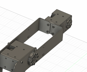
Step 1
Attach one Shoulder to the front of Servos 2 and 3 using the 8 black spacers and 8 M2.5 x 17mm screws that are included with the servos. [~12 minutes]

- Unscrew the screws in the servo body, and put in 8 black spacers (included with Servos) before putting on the Shoulder
- If you are looking at the Shoulder like an L, the idler side (back) should be facing you
- Servo 3 should be on the small part of the L, and Servo 2 should be at the base of the long part
Step 2
Flip it over and wire Servos 2 and 3 [~6 minutes]
- "Left wire" and "Right wire" are when looking at the back (idler) side of the Servo, with the LED at the top
- Servo 2
- The right wire passes through the body and goes to the left hole on Servo 3
- The left wire is the one already connected to Servo 1, it passes through the curved slot on the pan plate. You will have to have it connected to the base as the arm is built.
- Cover with small plastic cover included in the Servo box
- Servo 3
- The left wire connects to the right hole on Servo 2
- The right wire passes through the center back idler and eventually goes to the right hole on Servo 4
- Make sure the wires are not twisted or squished by the servo case
- Cover with small plastic cover included in the Servo box
Step 3
Attach other Shoulder to the back of Servo 2 and Servo 3 using 8 black spacers and 8 M2.5 x 17mm screws included with the servos [~13 minutes]

- Unscrew the screws from the back of the servos, and put in 8 black spacer rings (included with Servos) before attaching the Shoulder
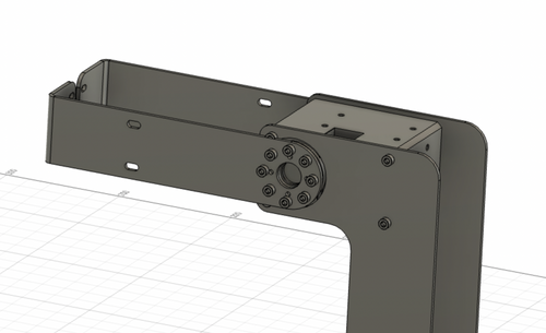
Step 4
Attach both Bearing Mounts to the horn and idler of Servo 2 using 2 Servo Washers and 16 M2.5 x 5mm screws, which are included with the servo and idler [~10 minutes]
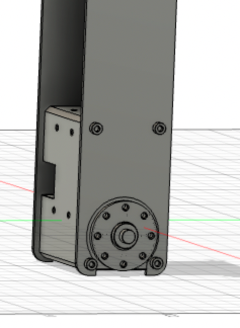

- Make sure the notch on the servo horn is pointing towards the LED on the servo. The notch should be pointing towards the bottom of the Bearing Mounts.
- Put a laser cut Servo Washer in between the horn/idler and the bearing mount
- IMPORTANT: The M2.5 x 5mm screws are the slightly longer included screws. There are two sizes with a very slight difference in length and they are all mixed together. If you can’t get a screw to screw in, you probably grabbed a shorter one.
Step 5
Attach Bearing Mounts to the Pan Plate, with 6 or 4 M2.5 x 12mm screws and 6 or 4 M2.5 nuts [~12 minutes]

- The screws should be on the bottom of the Pan Plate and nuts on the top of the Bearing Mounts
- If you have a bearing with 4 holes on each ring, use 4 screws/nuts, and if you have one with 6 holes use 6 (as pictured)
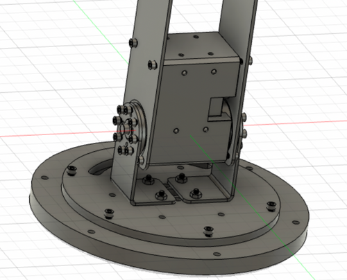
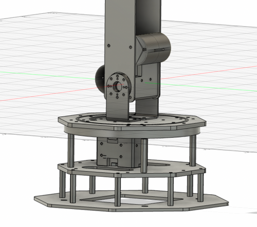
Step 6
Attach the Pan Plate on top of the Upper Center Mount using 6 M3 x 16mm screws and 6 M3 nuts [~8 minutes]

- The four screws from the last step should fit in the four large holes in the Upper Center Mount
- The nuts should fit into the hexagon holes in the lower center mount
- You may have to rotate Servo 1 to be able to insert all of the nuts
- Don’t screw these screws in too tightly or the tension may restrict the motion of Servo 1
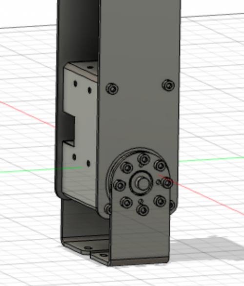
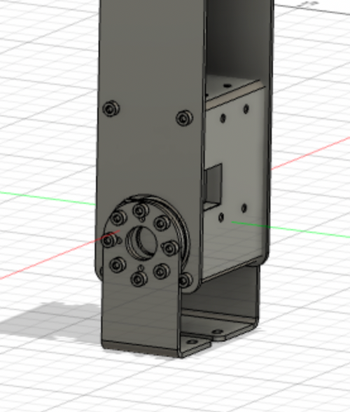
Step 7
Attach the Pan Cover to the outer ring of the bearing and into the standoffs on the top of the Middle Base using 6 or 4 M3 x 16mm screws [~2 minutes]
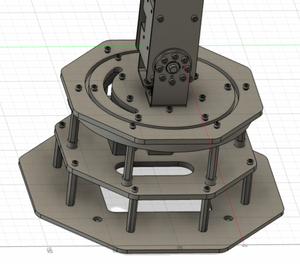
- move Pan Cover over the shoulder and onto the bearing
Step 8
Attach both Forearms to the horn and idler of Servo 3 using 2 Servo Washers and 16 M2.5 x 5mm screws, which are included with the servo and idler [~12 minutes]


- Once again, these are the longer of the 2 sizes of included screws
- Make sure the notch on the servo horn is pointing towards the LED on the servo, and you are attaching the forearm facing exactly in that direction
- The one on the idler is usually ForearmLowerHoles, and the one on the horn is ForearmUpperHoles, but either way would work
- Put a laser cut Servo Washer in between the horn/idler and the forearm
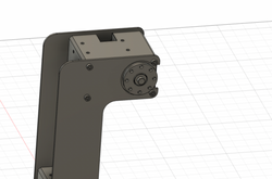
Step 9
Attach Servo 4 to the Forearms using 4 M2.5 x 4mm screws, which are included with the servo [~13 minutes]
- The M2.5 x 4mm screws are the longer of the 2 sizes of screws that come in the Servo 4 box
- The servo horn should face the same way as the ones on Servos 2 and 3
Step 10
Wire Servo 4
- The wire from Servo 3 (through the idler) should connect to the right hole of Servo 4 when looking at the idler sider with the LED on top
Step 11
Attach two Bumpers to the top and bottom of Servo 2 using 4 M2.5 x 3mm screws [~3 minutes]

- On the top use the two holes closer to the horn/idler, and on the back use the two holes further from the horn/idler
Continue on to the Head Page to move on to the final part of assembly.
Build Your Own Shutter Robot
- Laser Cut Pieces
- Water Jet Pieces
- 3D Printed Pieces
- 1. Set up Servos
- 2. Assemble Base
- 3. Assemble Arm
- 4. Assemble Head
- 5. Build E-Stop
- 6. Final Assembly
Gather Your Materials
Bill of MaterialsAssemble Your Robot
Install and Run the Software
Software Setup