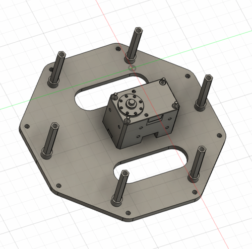
Base (Assembly Part 2)
Disclaimer: Shutter can be built using this bearing, which has 6 holes on each ring, or this one, which has 4. The images in this guide are using bearing with 6 holes, while the videos use the one with 4. The only differences between the two are the amount of hardware required, and which holes are used on the Middle Base, Pan Plate, and Pan Cover.
Step 1
Attach 8 30mm standoffs to the top of the Bottom Base using 8 M3x10 screws through the outer circle of 8 holes [~5 minutes]
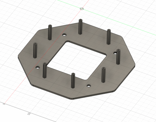
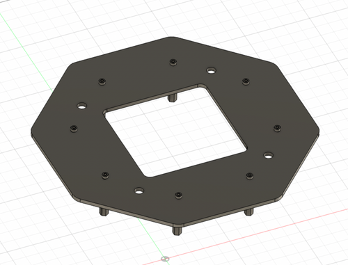
- If you have M/F 10mm standoffs and F/F 20mm standoffs instead of F/F 30mm standoffs, combine the two smaller ones here
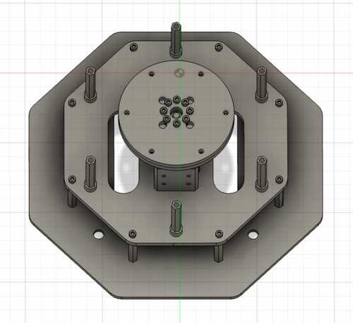
Step 2
Take 4 or 6 35mm standoffs, add 5 nylon spacers to each one, and attach to the top of the Middle Base through inner circle of 4 or 6 holes using 4 or 6 35mm standoffs. You will use a total of 20 or 30 nylon spacers. [~8 minutes]
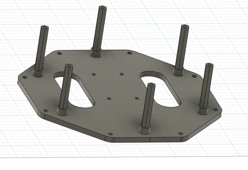
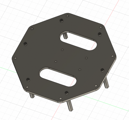
- If you have a bearing with 4 holes on each ring, use 4 standoffs, and if you have one with 6 holes use 6 (as pictured)
- If you have M/F 10mm standoffs and F/F 15mm standoffs instead of F/F 35mm standoffs, combine the two smaller ones here
Step 3
Wire Servo 1 and mount it to the top of the Middle Base using 4 M2.5 x 20 screws and 4 of the black spacers included with the servo. [~8 minutes]
- Wire Servo 1
- If you are looking at the back of the servo with the LED facing up
- Right wire: a 180mm wire with a brown JST-MOLEX connector included with Servo 1 that goes to the driver
- Left wire: a 180mm wire with two white JST-ST connectors included with Servo 1 that will go to Servo 2
- You don’t need the little plastic piece that covers the wires
- The driver wire passes through the right hole in Middle Base
- If you are looking at the back of the servo with the LED facing up

- The Servo Horn should be at the center of Middle Base
- Unscrew the 4 screws on the back of the servo, then insert included black spacers into the screw holes before screwing in the M2.5 x 20 screws
Step 4
Mount Bottom Base to the 30mm standoffs on the bottom of Middle Base using 8 M3 x 10mm screws. [~4 minutes]

Step 5
Attach Lower Center Mount and Upper Center Mount to Servo 1 using 8 M2 x 12mm screws [~4 minutes]

- Make sure the little notch on Servo 1 is still at the top
- The Upper Center Mount goes on top of Lower Center Mount, make sure the outer holes and hexagons line up! The holes on both parts should be in the arrangement they are in the images. The four larger holes on Upper Center Mount should make a square facing the front, and there should not be a hexagon directly at the top, above the notch.
- Be careful, because there are some ways of lining up the two pieces that are almost correct, but something is slightly off
- If you aren’t able to turn the servo horn using the mounts, loosen the screws slightly
Step 6
Mount Pan Plate to the inside ring of the bearing using 6 or 4 M3 x 16mm screws and 6 or 4 M3 nuts. [~6 minutes]


- The screws should be on top of the Pan Plate, with the nuts on the bottom of the bearing
- If there are notches on one side of your bearing, orient it so that the notches on the inner circle and facing down (on the side with the nuts)
Continue on to the Arm Page to move on to Part 3 of assembly.
Build Your Own Shutter Robot
- Laser Cut Pieces
- Water Jet Pieces
- 3D Printed Pieces
- 1. Set up Servos
- 2. Assemble Base
- 3. Assemble Arm
- 4. Assemble Head
- 5. Build E-Stop
- 6. Final Assembly
Gather Your Materials
Bill of MaterialsAssemble Your Robot
Install and Run the Software
Software Setup