Final Assembly
TODO: section summary
Connecting to the Robot

Software Installation
Shutter is controlled with a collection of ROS packages. To setup Shutter's ROS packages, follow the instructions outlined in the shutter-ros documentation.
Validate Servo Positions
After assembling the robot and installing the software, the positions of the servos should be validated.
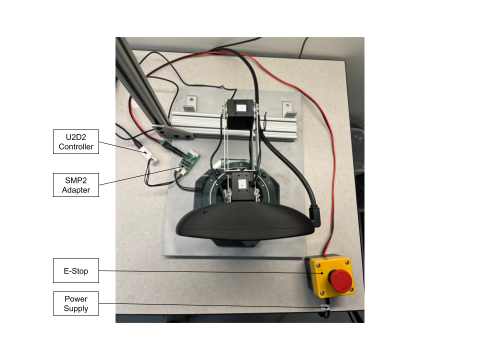
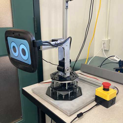
Connect the servos to a U2D2 controller and power supply. The robot should remain in a "resting" position, as pictured in the image below:

Inspect the servos with Dynamixel Wizard. Ensure that Operating Mode is set to Position control and the servo horn alignments are correct.
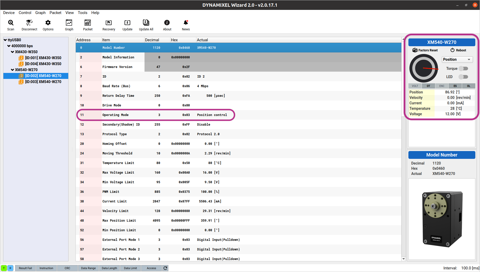
- The position for each servo can be read from the right panel of Dynamixel Wizard (highlighted in purple).
- In the resting position, the servo positions in degrees should be around:
- Servo 1: 0°
- Servo 2: 90°
- Servo 3: 90°
- Servo 4: 0°
- Note that there may be small (< 5°) discrepancies between the expected and actual positions, which are tolerable at this stage. Larger discrepancies indicate that the servo is not properly aligned, and the servo hardware needs to be corrected. Refer to the servo assembly document for instructions.
Adjust the robot to its "Home" or "Zero" configuration with MoveIt, using the shutter_moveit_config package. In the MotionPlanning RViz panel, select home as the Goal State, then click Plan & Execute.

- The following roslaunch command should be used:
$ roslaunch shutter_moveit_config demo.launch moveit_controller_manager:=ros_control
- Note that additional command-line arguments may need to be set, depending on the address of the USB serial device. The default is
/dev/ttyUSB0 - The robot should move to the home configuration, which corresponds to all servo positions set to 0°.
Ensure that the robot's pose matches the goal state in RViz:
- Note that very small (< 3°) discrepancies are tolerated, due to the servos' closed-loop controllers. Larger discrepancies indicate that the servo is not properly aligned, and the servo hardware needs to be corrected. Refer to the servo assembly document for instructions.
Build Your Own Shutter Robot
- Laser Cut Pieces
- Water Jet Pieces
- 3D Printed Pieces
- 1. Set up Servos
- 2. Assemble Base
- 3. Assemble Arm
- 4. Assemble Head
- 5. Build E-Stop
- 6. Final Assembly
Gather Your Materials
Bill of MaterialsAssemble Your Robot
Install and Run the Software
Software Setup