Head (Assembly Part 4)
Throughout assembly of the head, when screwing screws into the 3D printed pieces, the holes will be smaller than the diameter of the screw. This is so that the threads for the screws are created as you screw them in for a secure fit. Sometimes it is helpful to widen the hole a bit with an allen wrench, and then pre drill them with the screw first before screwing the component in. You might need a considerable amount of pressure, so use hex screwdrivers as opposed to allen wrenches if you have them.
Step 1
Take apart the Camera according to these instructions. Once the Camera is isolated, put 4 layers of black electrical tape over the blue LEDs on either side of the circuit board.

- IMPORTANT: Be very careful during Step 7, where you disconnect the USB connector. It is very easy to rip the entire connector off the board here. To avoid this, it is helpful to add a little glue to the base of the connector before you disconnect it.
- You could also remove the LEDs entirely using soldering tweezers or a soldering iron
Step 2
Solder Camera Vdd and GND to Display Vdd and GND

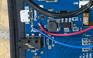

- In the image, the red wire is Vdd, and the blue wire is GND
Step 3
Place Camera in the Head Front, cover the back of it with tape, and then screw in Heat Sink on the back using 2 M3 x 10mm screws.
- Before attaching anything to the Head Front and the Head Back 3D printed pieces, you can optionally sand them to acheive a smoother finish.
Step 4
Attach Display to the Head Front using 4 M3 x 5mm screws.
Step 5
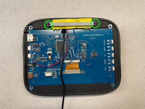
Attach the 2 Monitor Mounts to the Head Back using 4 M3 x 10mm screws.
- When looking at the back of the head, the camera wire should come out to the right of the Monitor Mounts (the opposite side from the hole for the HDMI cable)
Step 6
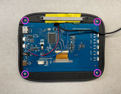
Attach the Head Front and the Head Back with 4 M3 x 15mm screws.

- If you intend on attaching anything to the top of the head, insert magnets into the slots at the top of the Head Back, and secure with super glue before closing up the head.
Step 7
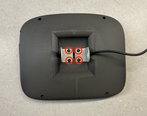
Attach the Monitor Mounts to the horn/idler of Servo 4 using 16 M2 x 3mm screws.
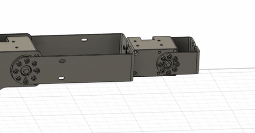
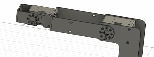
- The M2 x 3mm screws are the shorter of the 2 screw sizes included with Servo 4 and the HN12 Idler
- Make sure that the camera is at the top of the head
- Make sure the notch on the servo horn is pointing towards the LED on the servo, and you are attaching the monitor mounts facing exactly out
Step 8
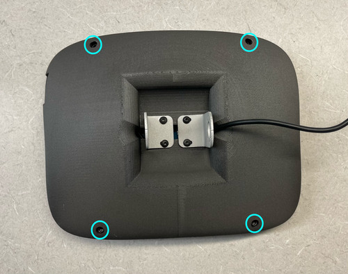
Attach Bottom Base to Aluminum Breadboard using 4 M6 x 12mm screws and 8 M6 washers (2 for each screw).
- Place two washers between the Bottom Base and the Aluminum Breadboard for each screw.
Your Shutter robot should now be completely assembled! You can move on to setting up the software.
Build Your Own Shutter Robot
- Laser Cut Pieces
- Water Jet Pieces
- 3D Printed Pieces
- 1. Set up Servos
- 2. Assemble Base
- 3. Assemble Arm
- 4. Assemble Head
- 5. Build E-Stop
- 6. Final Assembly
Gather Your Materials
Bill of MaterialsAssemble Your Robot
Install and Run the Software
Software Setup