Servos (Assembly Part 1)
All images on this page were sourced from the XM430-W210-T Servo Manual and the XM540-W270-T Servo Manual. These manuals contain more details about certain assembly steps, as well as more information about the servos.
Servos 1 + 4
Attach included Servo Horn HN12-N101 to both XM430-W210-T Servos (Servo 1 and Servo 4) with included M2.5x6 screw and Thrust Washer

- XM430-W210-T Servo Manual
- IMPORTANT: BE SURE TO LINE UP THE NOTCH ON THE SPLINE OF THE SERVO AND THE HORN - this should stay facing up (towards the side of the servo with the LED) throughout assembly

- Try to get the horn as flush to the servo face as possible
- The M2.5x6 is the smaller screw in the small ziplock bag with the black washers and the 2 screws in it
- Make sure to return all parts of the servo to the box before moving on to the next servo
Attach HN12-I101 Set idler to the back of Servo 4
- Unscrew the 4 corner screws on the back of the servo
- While pushing down on the white tab, use an allen wrench to pop out black circular cover from the inside

- Push the bearing down into the hole where the black cap came off, and ensure that it is flush with the servo case. Then attach the idler and the idler cap. (ignore the wiring in the assembly photo)

- Reattach back cover to Servo 4
- Put screws from the idler back in the HN12-I101 Set bag, and then put them into the Servo 4 box
Servos 2 + 3
Attach included Servo Horn HN13-N101 to both XM540-W270-T Servos (Servo 2 and Servo 3) with included M3x8 screw and Thrust Washer

- XM540-W270-T Servo Manual
- IMPORTANT: BE SURE TO LINE UP THE NOTCH ON THE SPLINE OF THE SERVO AND THE HORN - this should stay facing up (towards the side of the servo with the LED) throughout assembly
- Try to get the horn as flush to the servo face as possible, sometimes it is helpful to use the force of the screw to push the horn in
- The M3x08 screw is the large screw in the ziplock bag with black washers
Attach HN13-I101 Idler to the back of both servos, following the above idler diagrams
For Servo 3, break off the small piece to the right of the idler (when looking from the front) so that you can thread that wire through the idler before you put in the black plastic idler cap
- Attach the back of the wire to the right wire connector inside Servo 3
- The image below is from the servo documentation and shows how to wire through the servo, do not follow exactly because we want the right wire to pass through the idler (the diagram has the left one passing through)

- Make sure the wires aren’t twisted, you want the three to lay flat next to each other

- Reattach the back face
- If you haven't yet, now is a good time to update the firmware on the servos one by one before you daisy chain them together
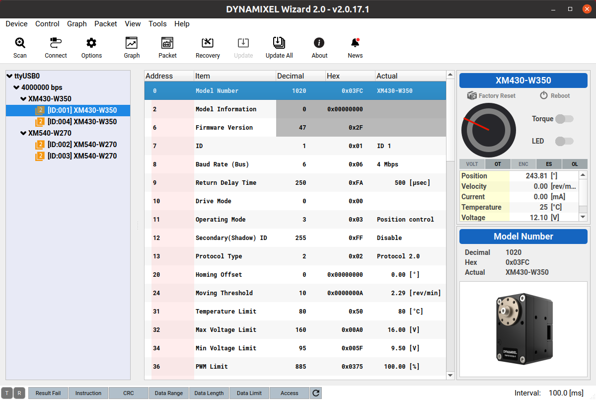
Servo Firmware and Configuration
The servo firmware and control table configuration can be set with the Dynamixel Wizard utility. After installing Dynamixel Wizard, connect the servos to your workstation via the U2D2 controller and to the power supply with the SMPS2 adapter.
Update the servo firmware from Protocol 1 to Protocol 2
- Protocol updates need to be applied to the servos one at a time (i.e., servos cannot be daisy-chained): Firmware Recovery
- If all of the servos have been updated to Protocol 2, further firmware updates can be applied simultaneously to all servos after they have been daisy-chained: Firmware Update All
Set ID's 1-4 with the Dynamixel Wizard control table
- The two XM430 servos should be set to ID 1 and ID 4
- The two XM540 servos should be set to ID 2 and ID 3
Set baud rate to 4 Mbps with the Dynamixel Wizard control table
- All servos should have their Baud rate set to 4 Mbps
- You should run the Dynamixel Wizard scan function to validate the servo firmware, ID and baud rate
Continue on to the Base Page to move on to Part 2 of assembly.
Build Your Own Shutter Robot
- Laser Cut Pieces
- Water Jet Pieces
- 3D Printed Pieces
- 1. Set up Servos
- 2. Assemble Base
- 3. Assemble Arm
- 4. Assemble Head
- 5. Build E-Stop
- 6. Final Assembly
Gather Your Materials
Bill of MaterialsAssemble Your Robot
Install and Run the Software
Software Setup