Emergency Stop Button
Components
E-stop button

E-stop contact block
White lock plate button

Button enclosure
Helpful Info: Button/switch datasheet
Other Materials
- ~47 inches of 16-gauge power wire cable
- RED 22-16awg crimp ring terminal (x2)
- DC barrel jack adapter - female
- DC barrel jack adapter - male
Building Instructions
Step 1
Unscrew the black, ribbed collar at the bottom of the e-stop button. Once this comes off, remove the metal plate at the bottom of the button as well.
Step 2
To place the button through the contact block, make sure that the red switch on the contact block is in the leftmost position.
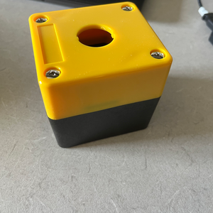
Step 3
Put the bottom end of the button through the hole in the enclosure. Replace the metal plate on the inside of the enclosure and screw it into place with the black collar, as shown in the image below.
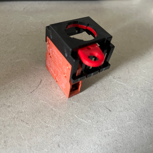
Step 4
Attach the contact block and turn the block’s red switch to the rightmost side in order to lock the button into place. The final assembly should look like the picture below.

Step 5
Drill holes into the black bottom half of the controller, as shown in the image.
- NOTE: - Use a 1/4" drill bit to pre-drill a smaller hole to prevent the plastic from splitting, and then make it bigger using a 5/16” drill bit.

Step 6
Now it is time to connect the power cable wires to the female barrel jack adapter. After separating the black and red wires, cut a few inches of the red wire off (this is how you will connect the positive wire across the switch).
Step 7
The switch infrastructure uses ring terminals. Thus, strip about 3/8” of one end of the red wire and use a crimping tool to attach a red ring terminal to the stripped end. In the same way, attach a red ring terminal to the red wire still attached to the black wire.
- NOTE: - This guide from Napa Online is particularly helpful for working with ring terminals: https://knowhow.napaonline.com/how-to-use-crimp-terminals-the-right-way/
Step 8
Strip about 1/4” of the other end of the red piece of wire and the longer end of the black wire. The barrel jack adapters use screw terminals, so loosen the screws, push the stripped wires inside the corresponding terminals, and tighten the screws. Since screw terminals have the potential to come loose, adding a dab of hot glue to each connection ensures the wires will not slip out.
Step 9
Hot glue the female barrel jack adapter to the bottom of the enclosure so that the smaller end fits through the drilled hole. Next, thread the remaining cable through the other drilled hole.
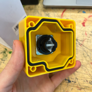
Step 10
Loosen the screws of the e-stop switch and place the ring terminals inside so that the screws go through the terminals. Then, tighten the screws and ensure that the terminals are not moving at all. After steps 6-10, you should have an e-stop that looks like the picture below.

Step 11
Secure the bottom and top halves of the enclosure using the screws that came with it.
Step 12
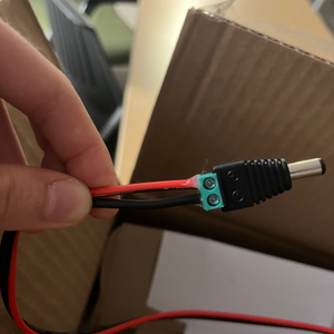
Finally, attach the male barrel jack adapter to the exposed end of the power wire cable. Follow the same directions as in step 8. The male barrel jack attachment should look like the following picture.
You have finished your e-stop button!
Build Your Own Shutter Robot
- Laser Cut Pieces
- Water Jet Pieces
- 3D Printed Pieces
- 1. Set up Servos
- 2. Assemble Base
- 3. Assemble Arm
- 4. Assemble Head
- 5. Build E-Stop
- 6. Final Assembly
Gather Your Materials
Bill of MaterialsAssemble Your Robot
Install and Run the Software
Software Setup